I bought my first Arduino board a couple of years ago. It didn’t take long before I wanted to have some kind of network capability for my board so I bought some ESP8266 01 WiFi modules afterwards. Then I learned that ESP8266s are actually powerful enough to run simple codes. I have an obsession with overhead in my personal projects so I realized that I did not need the Arduino anymore and could ditch it.
One of the things I really wanted to make was a small enough board with sensors for temperature, humidity, and CO2 on it which can send data over WiFi. The idea is to build several of these and put them in each room.
The boards need to be:
-
Small - low profile: I don’t want to have an eyesore in every room.
-
Low power: Under 1W on average at the very least, since I want to have a bunch on them.
-
Powered over sockets: I don’t want to change batteries.
After delaying this idea for years, I finally got to finishing it and I want to write about the problems that I had and mistakes I made along the way. Hopefully, it will help someone who wants to make something similar.
Hardware
The parts I used are:
-
1x DHT22 temperature and humidity sensor
-
1x ESP8266-01 WiFi module
-
1x Breakout adapter for ESP8266
-
1x Micro USB to DIP adapter
-
1x 5V to 3.3V voltage regulator (ESP8266 cannot handle 5V)
-
1x 10kΩ resistor (for pulling up GPIO0 on ESP8266)
The most important part of the board is the breakout adapter for ESP8266. It makes the ESP modules pluggable, thus re-programmable if need be, e.g. if you want to change the id of the board or the update interval. I also considered having an adapter for the DHT22 but dropped the idea because I don’t think (or I hope) that I will be replacing it with another sensor.
Initially, I wired everything on a breadboard. I was thinking about adding a CO2 sensor later but I left it out. Maybe I’ll add one for the next board I build.
Schematics
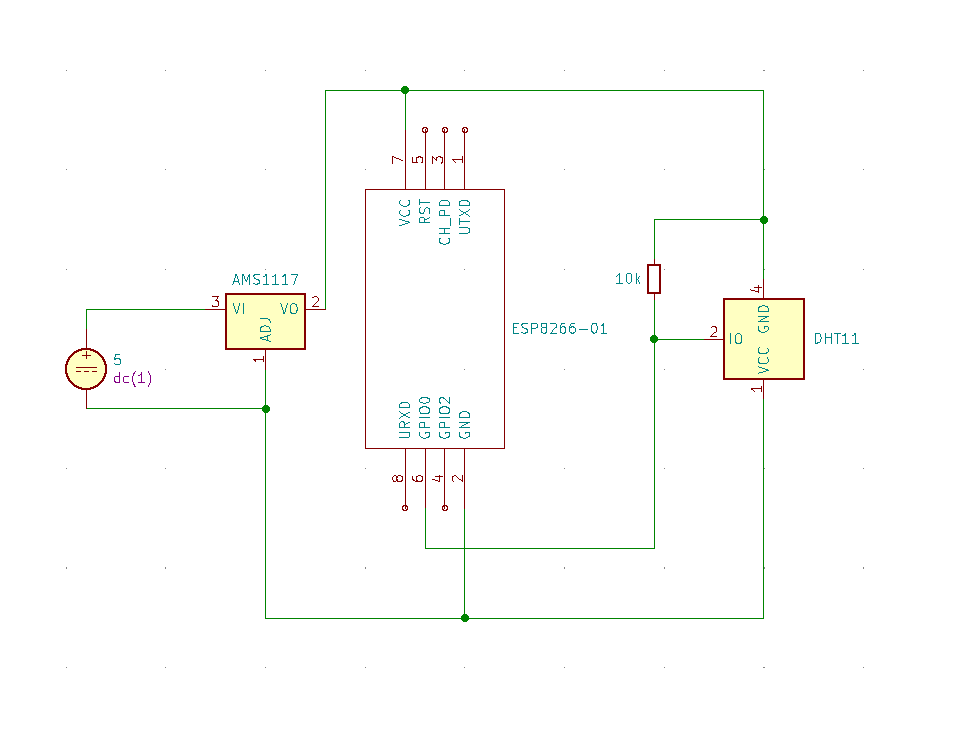
The circuit is very simple. I actually created the schematics below just for this post. The power comes from a 240V to 5V USB adapter which I bought. The 5V source is the adapter piece for the board. KiCad did not have DHT22 so I used DHT11 instead in the schematics. It makes no practical difference in the circuit though. DHT22 is just a more precise/sensitive version of DHT11.

The most important part is the pull-up resistor for the GPIO0 pin on ESP8266. The module has a problem starting up properly if this pin is not set to high on startup.
Code
The code itself is trivial. There are libraries for controlling ESP8266, DHT22, for handling the UDP request etc.
#include <ESP8266WiFi.h>
#include <WiFiUdp.h>

#include <DHT_U.h>
#include <DHT.h>

#define DHTPIN 0
#define DHTTYPE DHT22
DHT dht(DHTPIN, DHTTYPE);

WiFiClient client;
WiFiUDP udp;
char* server ="<ip or domain of the server>";
String id = String("<any id you want to assign to this hardware>");
unsigned int port = 8094;

void setup() {
  Serial.begin(9600);
  Serial.println("Ready");
  Serial.println("Connecting to WiFi");
  WiFi.mode(WIFI_STA);
  WiFi.begin("<your-wifi-name>", "<your-wifi-password>");
  while (WiFi.status() != WL_CONNECTED) {
    delay(5000);
    Serial.println("Waiting");
  }
  dht.begin();
  Serial.println("Connected to WiFi");
}

void loop() {
  float h = dht.readHumidity();
  float t = dht.readTemperature();
  String humPacket = String("hum,id=" + id + " value=" + h);
  String tempPacket = String("temp,id=" + id + " value=" + t);
  Serial.println(humPacket);
  Serial.println(tempPacket);
  udp.beginPacket(server, port);
  udp.write(humPacket.c_str());x
  udp.endPacket();
  udp.beginPacket(server, port);
  udp.write(tempPacket.c_str());
  udp.endPacket();
  delay(60000);
}
The real important part is the id. That’s how you identify the sensor once it starts sending data. The data sent to the server is formatted in InfluxDB line protocol.
Architecture
The way I set it up requires two machines. One is the board with the sensor itself, the other one is some kind of server. I use make Raspberry Pi 3 for this. I installed InfluxDB and Telegraf on the server. Telegraf listens to udp packets on port 8094, parses the data that comes in a writes it to InfluxDB. I’m currently using Grafana to display the data in a human-friendly way.

Currently, the retention policy of InfluxDB is set to 2 days. This limits the amount of storage the data uses and hopefully helps mitigate the dreaded damage on the SD card due to excessive read/write operations.
Problems with the Breadboard
There was a significant problem with the breadboard setup. I was having problems delivering a steady 3.3V to ESP8266. As a result, I either had to connect/disconnect the plug several times until the module was working properly. Even in these cases, moving the setup could cause the loss of functionality, and often it simply stopped working after 5-6 hours. After testing and changing several jumper cables, I finally had a board that worked most of the time. It was, however, still not 100% stable and reliable. I tried using pull-up resistors for the pins RX, GPIO0, GPIO2, RST, and CH_PD. I was worried that there was something with the way I wired the setup.
Soldering
It turns out that my problems were cased entirely by the breadboard. Ever since I soldered it together, everything works continously the first time I plug it in. I only used a pull-up resistor for the GPIO0 pin, since it is connected to the sensor and I had problems getting clean values out of it in the past (DHT22 apparently has a pull-up resistor built-in, but it doesn’t seem to hurt to have another one).

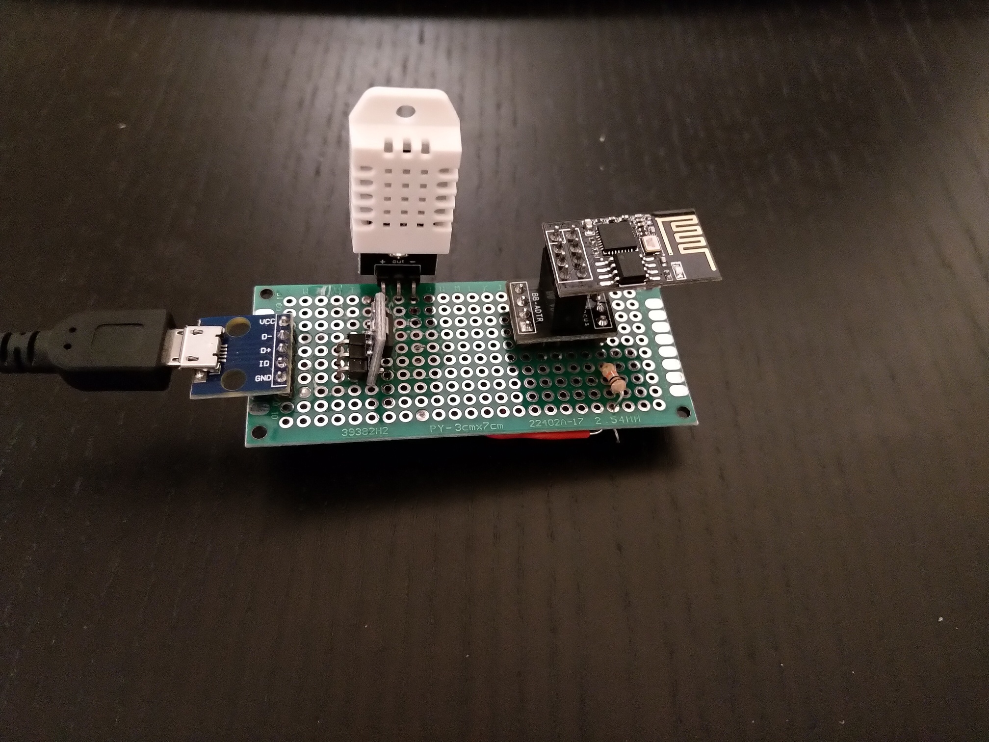
Figure 1: Front side which looks fairly clean
Soldering the wires was somewhat difficult. I already killed another board by trying to bridge the gaps with solder so this time I used wires. Also, I found out the hard way how difficult desoldering is so this time I tried using as little solder as possible for the job. This immediately paid out when I realized that I had wired the sensor the wrong way. Thankfully, it only took a few minutes to fix the mistake.

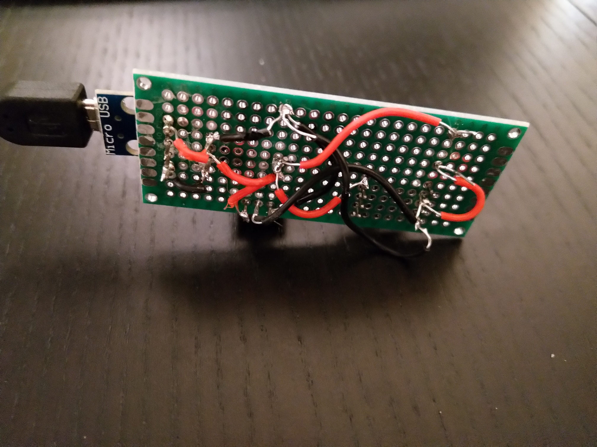
Figure 2: The back side looks quite sloppy. Also I messed up black/red wires from USB adaptor to voltage regulator.
There is a little bit of dried flux on the board. I will try removing it with alchohol.
Result
The board is working quite well despite of my shoddy soldering job. It uses on average 0.4W of power which is well within my parameters. What it is missing right now is an aesthetically acceptable case. I have been using this board for over a week now and I have not experience any problems with it.
Mistakes
My biggest mistake was to use micro USB for powering the board instead of USB-C. The way micro USB cables are attached, they tend to get stuck on the adapter and damage it while trying to remove. I already ruined two USB adapters because of this.